Table of Contents
1. Introduction
In modern power systems, grounding systems are fundamental components that ensure electrical safety and equipment protection. The basic concept of grounding is to connect electrical equipment to the ground, forming a safe circuit to prevent electrical accidents. Grounding not only protects equipment and reduces electromagnetic interference but also provides safety in extreme conditions, such as lightning strikes. Therefore, understanding the design, installation, and maintenance of grounding systems is crucial for electrical engineers and related professionals.
2. Types of Grounding Systems
In power supply systems, grounding systems can be categorized into several types:
2.1 System Grounding
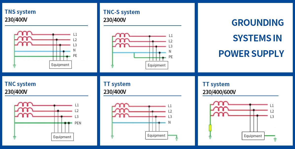
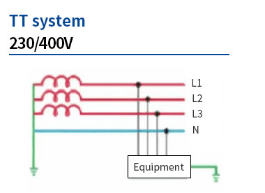
TT System: In a TT system, the neutral point of the power supply is directly grounded, while the load’s grounding is achieved through independent grounding electrodes. The advantage of this system lies in its good protection, making it suitable for general residential and commercial buildings.
2.2 TN System
The TN system is a common grounding method, divided into three subtypes: TN-S, TN-C, and TN-C-S. Each subtype has its unique characteristics and applications.
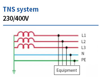
2.2.1 TN-S System
In a TN-S system, the neutral point of the power supply is directly grounded, and the neutral (N) and protective earth (PE) conductors are separate. This separation provides better safety and reliability. The advantages include:
- Fault Safety: Because the neutral and grounding conductors are separate, if one fails, the other can continue to operate normally, reducing the risk of electric shock or short circuits.
- Reduced Electromagnetic Interference: The separation of the grounding and neutral conductors effectively reduces electromagnetic interference, improving equipment performance, especially in sensitive devices requiring high power quality.
- Wide Application: TN-S systems are widely used in industrial and commercial buildings, particularly where high safety requirements are necessary.
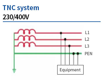
2.2.2 TN-C System
In a TN-C system, the neutral (N) and protective earth (PE) conductors are combined into one conductor called the PEN conductor. The characteristics include:
- Simplified Wiring: By merging the neutral and grounding conductors, the TN-C system reduces the number of conductors needed, lowering installation costs and space requirements.
- Suitability for Low Voltage Systems: TN-C systems are typically used in low voltage distribution systems, especially when the loads are relatively small.
- Potential Risks: While TN-C systems can reduce costs, the failure of the PEN conductor can pose safety hazards. Therefore, careful design and installation are critical to ensure safety.
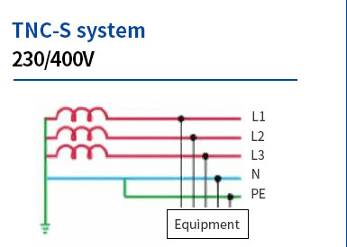
2.2.3 TN-C-S System
The TN-C-S system combines aspects of both TN-C and TN-S systems. In the TN-C-S system, the neutral and protective earth conductors are merged into a PEN conductor at one point, while they are separated at other points. The characteristics include:
- Flexibility: The TN-C-S system provides significant flexibility in wiring design, suitable for various types of loads and devices.
- Enhanced Safety: By separating the PEN conductor into N and PE near the load center, the TN-C-S system improves safety and reduces fault risks.
- Widespread Use: The TN-C-S system has become a widely adopted grounding method in modern buildings and industrial applications, particularly in large commercial complexes.
2.3 IT System
In an IT system, the neutral point is not grounded or is grounded through high impedance. This system is suitable for supplying power to critical equipment, minimizing the risk of damage during faults, but it requires higher technical standards and maintenance.
3. Components of Grounding Systems
Grounding systems consist of several key components:
3.1 Grounding Electrodes
Grounding electrodes are the components that connect electrical current to the ground, including grounding rods, grounding grids, and grounding plates. The materials used for grounding electrodes are typically copper-clad steel or stainless steel to enhance corrosion resistance and conductivity.
3.2 Grounding Conductors
Grounding conductors connect electrical equipment to grounding electrodes, serving as a conductive pathway. When selecting grounding conductors, factors like conductivity, mechanical strength, and corrosion resistance should be considered. Copper conductors are generally preferred.
3.3 Grounding Connections
Ensuring secure connections between the various components of the grounding system is crucial. This includes using appropriate connectors, maintaining good contact, and minimizing contact resistance. The quality of grounding connections directly affects the performance of the grounding system.
4. Design Principles of Grounding Systems
Designing an effective grounding system requires adherence to some fundamental principles:
4.1 Design Standards and Regulations
When designing grounding systems, it is essential to comply with relevant international and national standards, such as IEC 60364 and GB 50057. These standards provide requirements for the design, installation, and testing of grounding systems to ensure safety and reliability.
4.2 Grounding Resistance Requirements
An ideal grounding resistance value is typically less than 4Ω to ensure effective operation of the grounding system during faults. High grounding resistance may prevent fault currents from safely directing to the ground, increasing the risk of accidents.
4.3 System Layout
The layout design of the grounding system should be reasonably planned based on equipment type, electrical load, and environmental conditions. The arrangement of grounding electrodes should ensure coverage for all equipment needing grounding and avoid interference with other electrical systems.
5. Installation of Grounding Systems
The installation of grounding systems should strictly follow the design plan and standards:
5.1 Installation Process
The installation process for grounding systems typically includes the following steps:
- Design Planning: Design based on equipment layout and electrical load requirements.
- Material Selection: Choose appropriate grounding electrodes, conductors, and connectors according to standards.
- On-Site Construction: Implement the installation of grounding electrodes and connections as per the design.
- Testing and Verification: Conduct grounding resistance tests after installation to ensure compliance with design requirements.
5.2 Installation Considerations
During installation, the following considerations should be noted:
- In humid or corrosive environments, select appropriate materials to prevent performance degradation of the grounding system.
- Ensure secure connections of grounding conductors to avoid reduced effectiveness due to looseness.
- Conduct timely on-site tests upon completion to ensure system safety.
5.3 On-Site Testing
Conducting grounding resistance tests after installation is a key step to ensure the system’s effectiveness. Use a grounding resistance tester to measure the resistance value of the grounding system and compare it with design requirements to ensure it remains within a safe range.
6. Maintenance and Testing of Grounding Systems
Regular maintenance and testing of grounding systems are vital for ensuring their long-term effective operation:
6.1 Regular Inspections
Regularly inspect the condition of grounding electrodes, conductors, and connections and promptly address any issues. Maintenance of grounding systems is especially important in humid or corrosive environments.
6.2 Testing Methods
Common methods for testing grounding systems include:
- Grounding Resistance Testing: Measuring the grounding system’s resistance values using a grounding resistance tester.
- Grounding Continuity Testing: Ensuring the continuity of grounding conductors to prevent failures due to poor contact.
6.3 Documentation and Reporting
Maintenance and testing results should be documented in detail for future tracking and analysis. Establishing a comprehensive documentation system helps identify problems in a timely manner and implement improvements.
7. Role of Grounding Systems in Power Supply Safety
The effective operation of grounding systems plays a crucial role in the safety of power supply systems:
7.1 Preventing Electric Shock
An effective grounding system can safely direct leakage currents into the ground, reducing the risk of electric shock to personnel.
7.2 Protecting Equipment
Grounding systems can effectively prevent damage to equipment from overvoltage and lightning strikes. Especially during thunderstorms, a well-designed grounding system can safely divert lightning currents into the ground, protecting equipment and ensuring normal operation.
7.3 Reducing Electromagnetic Interference
Good grounding can minimize the impact of electromagnetic interference on equipment and systems, enhancing overall system stability. This is particularly important for sensitive devices such as computers and communication equipment.
8. Future Trends and Technologies
As technology evolves, grounding systems continue to advance:
8.1 Smart Grounding Systems
Utilizing advanced monitoring technologies to real-time monitor the status of grounding systems can provide timely alerts before faults occur, enhancing overall system safety.
8.2 Renewable Energy and Grounding
In renewable energy systems (such as solar and wind), grounding designs must consider new technical requirements to ensure safe operation of equipment. This will promote the safety and reliability of renewable energy systems.
9. Conclusion
Grounding systems play an indispensable role in power supply systems, ensuring electrical safety and equipment protection while providing a safe working environment for personnel. Therefore, following relevant standards and requirements is crucial for the design, installation, and maintenance of grounding systems to ensure their effectiveness and reliability. Electrical engineers and technicians should regularly update their knowledge to adapt to changing technologies and standards, ensuring the safe and stable operation of electrical systems.
10. Appendices and References
Related Standards and Regulations:
- IEC 60364: Safety standards for electrical installations.
- GB 50057: Codes for lightning protection design in buildings.
Recommended Reading:
- “Electrical Grounding Techniques”: A comprehensive book on the design and application of grounding systems.
- “Electrical Safety Handbook”: Provides extensive information on electrical safety and grounding systems.
If you have any further questions about grounding systems or any aspect of power supply, or if you need professional advice and support, please feel free to contact us. Our team is committed to providing you with assistance to ensure your electrical safety and equipment protection needs are met. Thank you for your attention and support!