Easy to install——35mm DIN rail installation design.
Easy to judge the condition of the equipment——Visual Indicator Window.
Easy to replace——Pluggable module.
Equipped with monitoring and feedback functions——Optional with remote signaling.
Classl·Classll·Type 1 Type 2
Location of Use: Main Distribution Boards
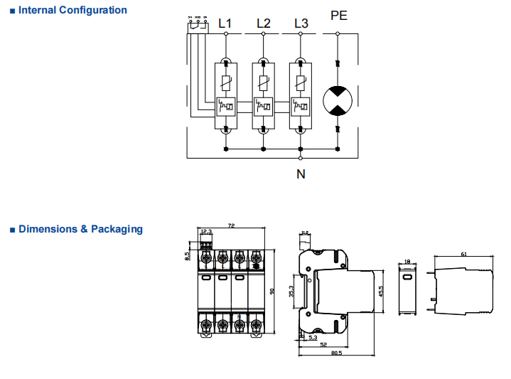
Mode of Protection: L-N, N-PE
Surge Ratings: Limp= 12.5 kA(10/350 μs)
Ln= 20 kA (8 /20 μs)
IEC/EN/UL Category: Class l+ll /Type 1+2
Protective Elements: High Energy MOV and GDT
Housing: Pluggable Design
Compliance: lEC 61643-11:2011
EN 61643-11:2012
UL 1449 4th Edition
Easy to install——35mm DIN rail installation design.
Easy to judge the condition of the equipment——Visual Indicator Window.
Easy to replace——Pluggable module.
Equipped with monitoring and feedback functions——Optional with remote signaling.
| ■ Technical Data | ||||||
| IEC Electrical | 75 | 150 | 275 | 320 | ||
| Nominal AC Voltage (50/60Hz) | Uo/ Un | 60 V | 120 V | 230 V | 230 V | |
| Maximum Continuous Operating Voltage (AC) | (L-N) | Uc | 75V | 150 V | 275 V | 320 V |
| (N-PE) | Uc | 255 V | 255 V | 255 V | 255 V | |
| Nominal Discharge Current (8/20 μs) | (L-N) / (N-PE) | In | 20 kA / 50 kA | |||
| Maximum Discharge Current (8/20 μs) | (L-N) / (N-PE) | Imax | 50 kA /100 kA | |||
| Impulse Discharge Current (10/350 μs) | (L-N) / (N-PE) | Iimp | 12.5 kA / 50 kA | |||
| Specific Energy | (L-N) / (N-PE) | W/R | 39 kJ/Ω / 625 kJ/Ω | |||
| Charge | (L-N) / (N-PE) | Q | 6.25 As / 25 As | |||
| Voltage Protection Level | (L-N) / (N-PE) | Up | 0.7 kV / 1.5 kV 1 kV / 1.5 kV 1.5 kV / 1.5 kV 1.6 kV / 1.5 kV | |||
| (N-PE) | Ifi | 100 ARMS | ||||
| Response Time | (L-N) / (N-PE) | tA | < 25 ns / < 100 ns | |||
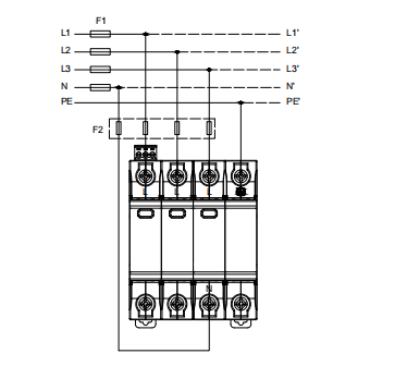
| Back-Up Fuse (max) | 315 A / 250 A gG | |||||
| Short-Circuit Current Rating (AC) | (L-N) | ISCCR | 25 kA / 50 kA | |||
| TOV Withstand 5s | (L-N) | UT | 114 V | 180 V | 335 V | 335 V |
| TOV 120min | (L-N) | UT | 114 V | 230 V | 440 V | 440 V |
| mode | Withstand | Safe Fail | Safe Fail | Safe Fail | ||
| TOV Withstand 200ms | (N-PE) | UT | 1200 V | |||
| UL Electrical | ||||||
| Maximum Continuous Operating Voltage (AC) | (L-N) / (N-PE) | MCOV | 75 V / 255 V | 150 V / 255 V | 275 V / 255 V | 320 V / 255 V |
| Voltage Protection Rating | (L-N) / (N-PE) | VPR | 330 V / 1200 V | 600 V / 1200 V | 900 V / 1200 V | 1200 V / 1200 V |
| Nominal Discharge Current (8/20 μs) | (L-N) / (N-PE) | In | 20 kA / 20 kA | 20 kA / 20 kA | 20 kA / 20 kA | 20 kA / 20 kA |
| Short-Circuit Current Rating (AC) | (L-N) | SCCR | 100 kA | 200 kA | 150 kA | 150 kA |
| Mechanical & Environmental | ||||||
| Operating Temperature Range | Ta | -40ºF to +158ºF [-40ºC to +70ºC] | ||||
| Permissible Operating Humidity | RH | 5%…95% | ||||
| Atmospheric pressure and altitude | 80k Pa … 106k Pa / -500 m…… 2000 m | |||||
| Terminal Screw Torque | Mmax | 39.9 Ibf·in[4.5 Nm] | ||||
| Conductor Cross Section (max) | 2 AWG (Solid, Stranded) / 4 AWG (Flexible) 35 mm² (Solid, Stranded) / 25 mm²(Flexible) |
|||||
| Mounting | 35 mm DIN Rail, EN 60715 | |||||
| Degree of Protection | IP 20 (built-in) | |||||
| Housing Material | Thermoplastic: Extinguishing Degree UL 94 V-0 | |||||
| Thermal Protection | Yes | |||||
| Operating State / Fault Indication | Green ok / Red defect | |||||
| Remote Contacts (RC) RC Switching Capacity RC Conductor Cross Section (max) |
Optional AC: 250V / 0.5 A; DC: 250V / 0.1 A;125V / 0.2 A;75V / 0.5 A 16 AWG (Solid) / 1.5 mm²(Solid) |
|||||

We offer a full range of customised services, working closely with our customers every step of the way, from concept design to final delivery.
Our team is always guided by the needs of our customers, providing professional consultation and support to ensure your satisfaction.
We know that every business is unique, so we offer customized services to ensure that our products perfectly match your specific needs:
We constantly evaluate and improve our processes to ensure that we are delivering the most efficient and reliable electrical products on the market.